Optional Systems

Complete your solution with optional systems that improve performance, safety and efficiency

This page is under construction!

We are designing three separate pages for the Optional Systems section. VC, HC and VCB will each have their own dedicated webpage following the standard Optional Systems layout.

These pages will provide additional product information to clarify and support the Optional Systems listed on the individual product pages. Each product page will link directly to its corresponding Optional Systems page.

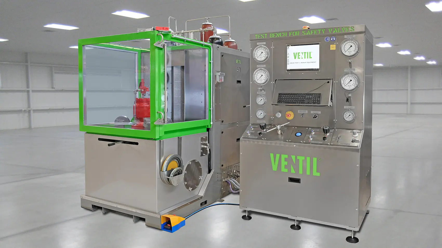
Compressor skid HPGC

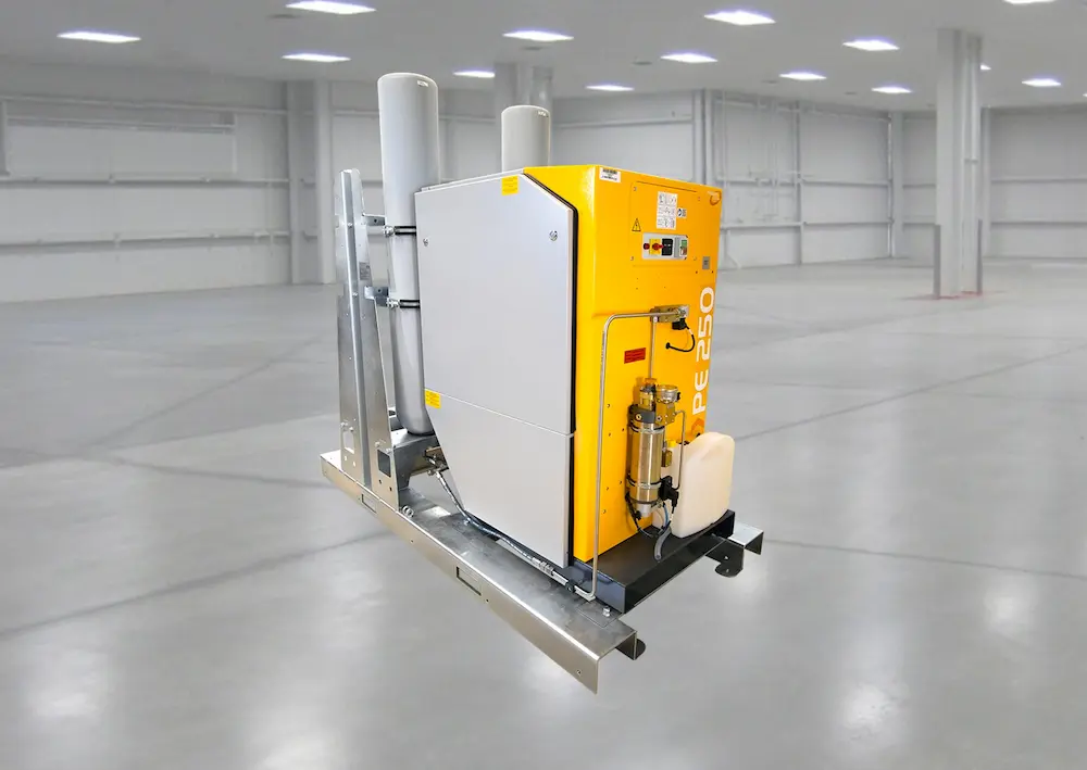
This electrically driven compressor delivers compressed air up to 300 bar (4,350 psi) and automatically fills the storage cylinders.

The standard system includes two 100-liter storage cylinders, expandable up to a maximum of six cylinders.

Designed for industrial applications, it features a low-noise enclosure, air intake filter, automatic condensate drain, cooling system and safety valve.

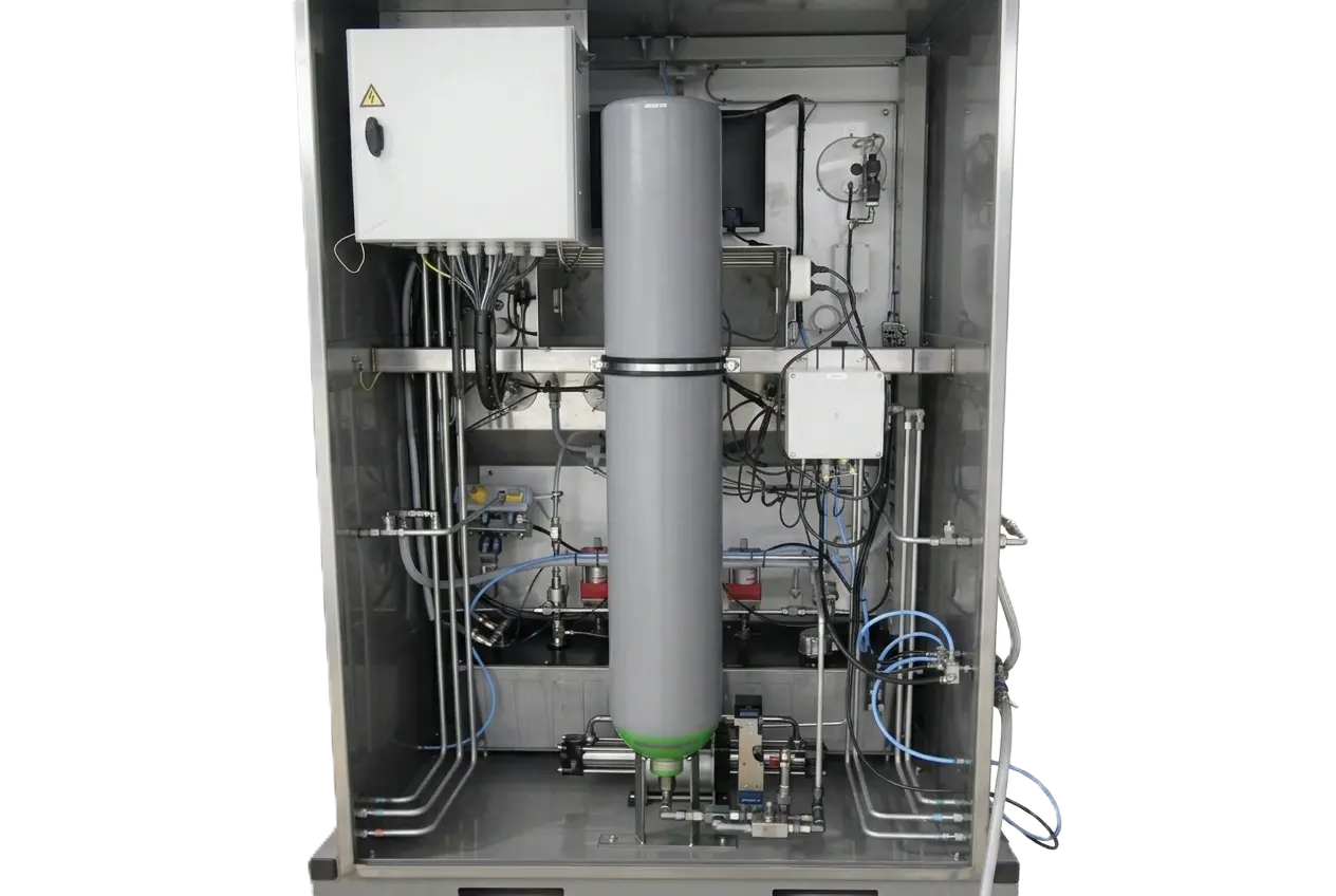
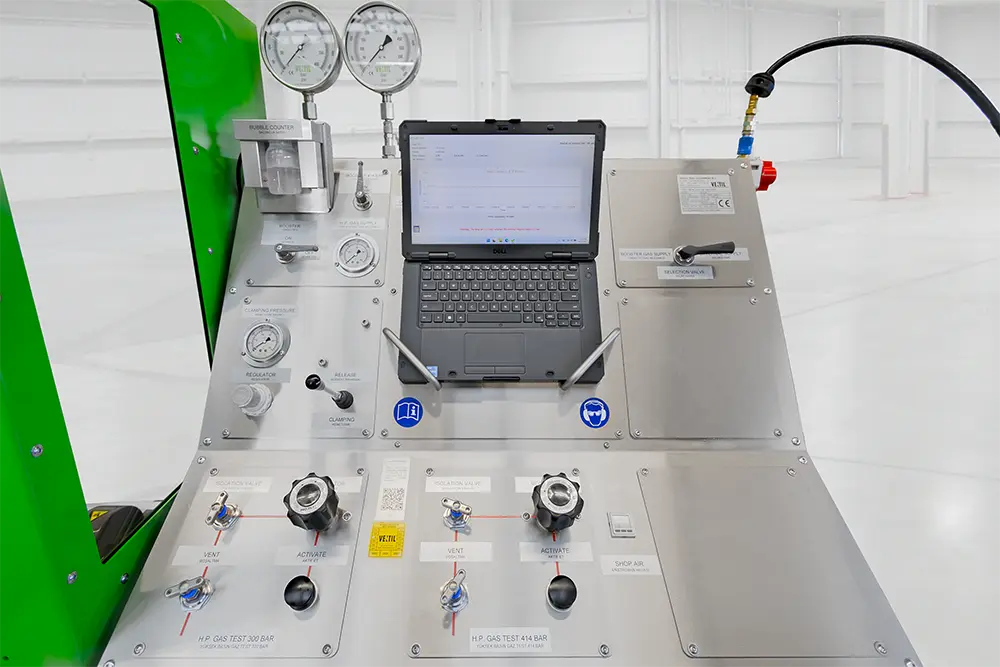
Gas booster system HPGB

The gas booster is a fully pneumatic, shop/utility air-driven pump system that compresses air to pressures of up to 300 bar (4,350 psi). The system automatically pressurizes a 50-litre storage cylinder.

Fully integrated into the test bench cabinet en control panel, the gas booster system includes a safety relief valve and a pilot-operated on/off switch, providing safe, reliable and efficient operation.

Test system up to 700 bar

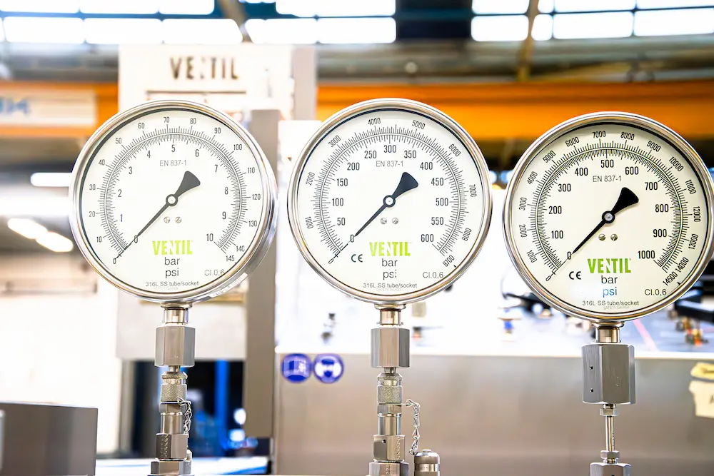
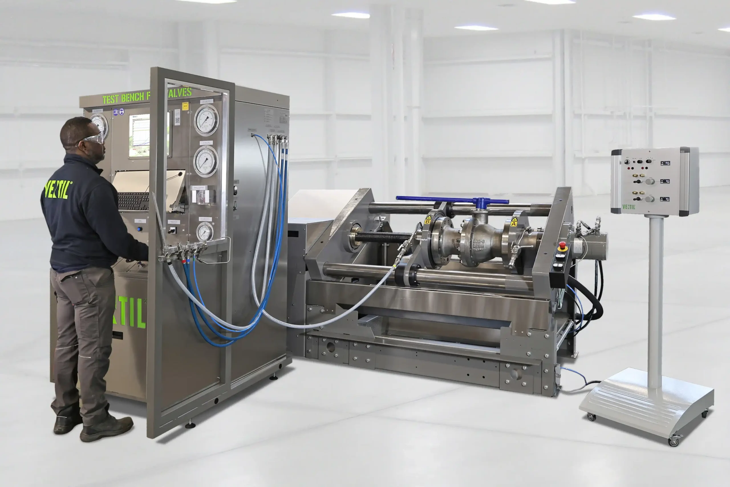
High-pressure gas and/or liquid test systems for testing at pressures of up to 700 bar (10,150 psi). These options features a fully integrated booster pump(s) that increases the externally supplied test gas to the required test pressure.

Designed for safe, accurate and user-friendly operation, the system includes dedicated controls, a stainless steel test adapter and precision pressure measuring instruments to ensure reliable test results.

Higher test-/set pressures available upon request.

Back pressure test system

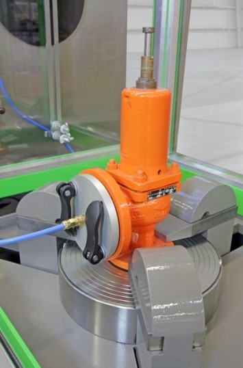
The Back Pressure Test System is designed to verify the tightness of pressure relief valves equipped with a gas-tight bonnet and cap. The valve is pressurized from the downstream side, typically at 3.5 bar (50 psi), to check the integrity of the valve body, bonnet and cap.

The system consists of a low-pressure air test system and dedicated back pressure plates, enabling the valve outlet flange to be sealed and pressurized quickly. Any leakage is easily detected by visual inspection and by monitoring the pressure gauge for pressure loss.

Pilot valve test system

The Remote Sensed Pilot Test System is designed for testing pilot-operated pressure relief valves with remote pressure sensing. By applying the control pressure from a remote connection instead of the valve inlet, the valve can be tested under conditions that closely simulate the actual process.

This method enables safe and accurate verification of the valve’s functionality, sensitivity, and set pressure without exposing the valve to full system pressure.

Automatic set pressure testing

The Automatic set Pressrure Test System ensures consistent and repeatable set pressure testing by automatically controlling the test pressure ramp rate. This eliminates operator influence and guarantees reliable test results.

The operator simply enters the expected set pressure, after which the system automatically increases the test pressure at a constant ramp rate (e.g. 2 psi/sec according to ASME, or a user-defined value). Once the valve starts to lift, the set pressure is detected automatically and the pressure supply is immediately stopped. The system is fully integrated into the test bench controls for fast and accurate testing.

Safety enclosures

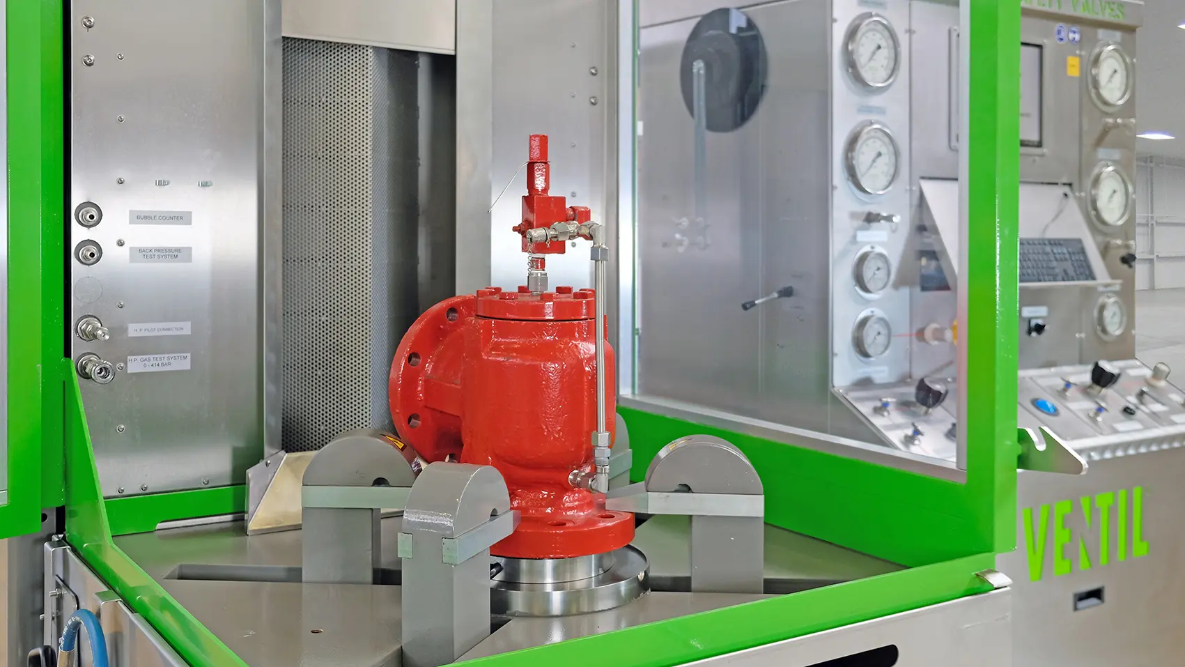
Every valve is different, with its own geometry, materials, operating pressure and stored energy.

To provide a practical and consistent safety solution, we have developed standardized safety enclosure concepts based on valve size and pressure class. These Safety Protection Levels (SPLs) are backed by comprehensive engineering analysis and validated against representative worst-case loading conditions, ensuring reliable protection across a wide range of applications.

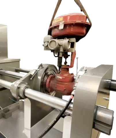
Actuator positioning system

The APS pedestal-mounted actuator control and test system allows users to verify operation, adjust valve trim, and test performance according to manufacturer specifications or process requirements.

The system enables full open/close testing and accurate verification of control responses using integrated pressure, signal, and electrical control systems for pneumatic actuators, positioners, solenoid valves, and current-controlled devices.

Automatic vacuum quick filling

The Automatic Vacuum Quick Filling System ensures a safe and accurate high-pressure liquid test by fully removing trapped air from the valve cavity, bonnet and internal spaces.

Especially for horizontally clamped valves without dedicated venting points, complete filling can be challenging. The system automatically creates a vacuum before switching to high-volume liquid filling, removing 95–100% of trapped air depending on the valve design.

HC1000

Seat leakage measuring system

Digital flow measuring system for classifying the liquid or gas seat leakage of shut-off and control valves, in accordance to the international test standards such as API 598, EN12266 and ANSI / FCI 70-2.

The system contains of a set of accurate, digital flow measuring instruments and enables the user to read the leakage in different units, such as; liters/min or cubic foot/hour.

Valve support - 5 ton

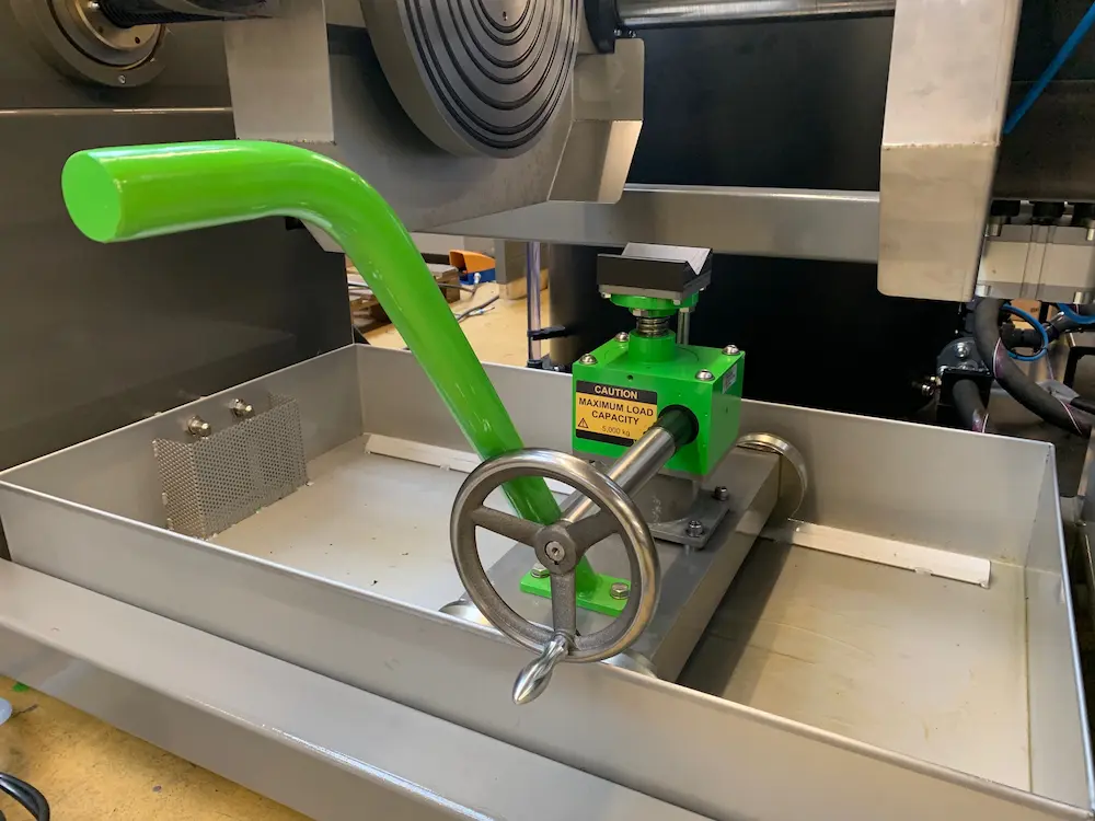
The HC clamping system can be equipped with a fully adjustable valve support to safely secure the valve during clamping and testing.

The valve support can be manually adjusted in both horizontal and vertical directions, allowing precise positioning for different valve sizes and configurations. 

It is suitable for loads up to 5 metric tons and is fitted with an interchangeable V-block for optimal support and flexibility.

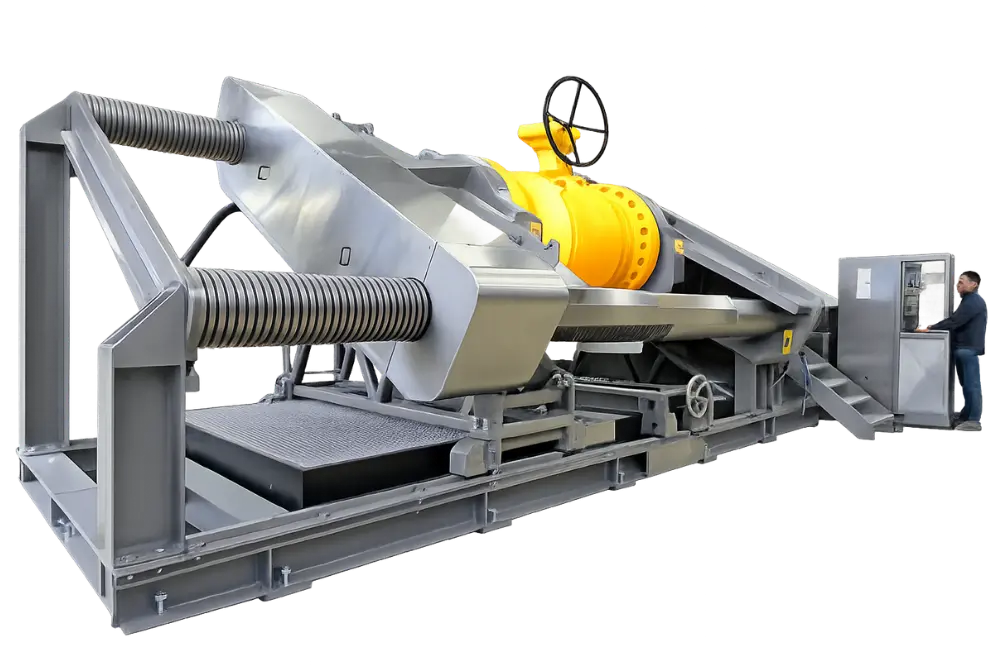
Inclined columns- angle 30°

The Inclined Column Configuration allows the HC clamping system columns to be positioned at a 30° angle instead of the standard parallel alignment.

By lowering the front column, valve loading, unloading, and inspection become easier. Please note that the raised rear column may limit access when testing valves with larger actuators or controls. 

First Name
Last Name
Company
Email Address
Notes / Remarks
CountryName